What this upgrade changes
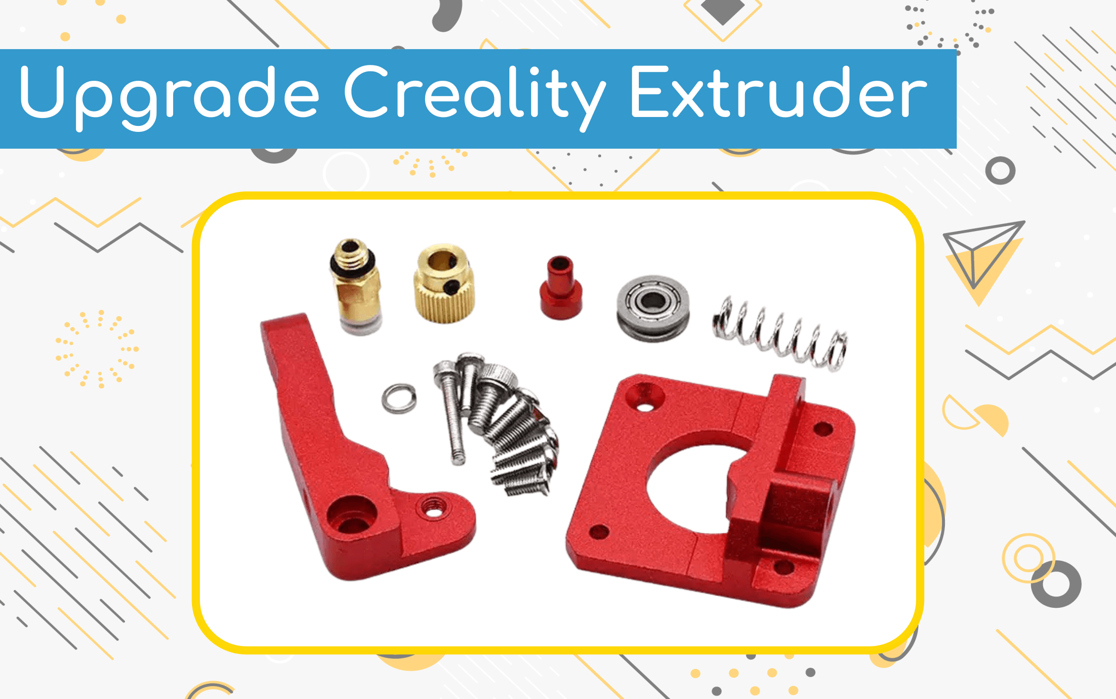
This guide replaces the moulded plastic Bowden extruder used on compatible Creality Ender 3 and CR-10 revisions with an aluminium assembly. The metal body can improve long-term reliability and filament grip, but it does not remove the need to align the drive gear, set spring tension and calibrate extrusion.
Check your printer first
| Platform or version | Status | Notes |
|---|---|---|
| Ender 3 / Ender 3 Pro | Supported | Applies to the common Bowden-style assembly; confirm your revision. |
| CR-10 family | Supported | Confirm motor shaft, mounting pattern and supplied hardware. |
| Direct-drive conversions | Check notes | The mechanical order and calibration may differ. |
| Ender 3 S1 and other integrated toolheads | Not supported | Do not assume this Bowden kit fits. |
Parts and tools
What you will need
- 1Compatible aluminium extruder kitCheck that the kit includes the correct screws, spring, arm and Bowden coupler.Required
- 12 mm ID / 4 mm OD PTFE Bowden tubeReplace it if the existing tube is worn, burnt or loose.Optional
- 1 setMetric hex keysMost kits use 2.0 and 2.5 mm sizes; verify before applying force.Required
- 1Small spannerFor the Bowden coupler if it cannot be loosened by hand.Required
Replace the extruder
Extruder replacement
- 01
Remove the Bowden connection
Unscrew the retaining coupling and withdraw the Bowden tube after filament is unloaded.
CheckpointThe tube and coupler are free without damaged threads. - 02
Remove the lever and spring
Compress the lever while removing its pivot screw, then lift away the arm and spring.
CheckpointThe spring is unloaded and the arm is separated safely. - 03
Remove the spring retainer
Use the correctly sized hex key and keep the original hardware organised.
CheckpointThe plastic retainer is free. - 04
Separate the stepper motor
Support the motor and remove the three mounting screws.
CheckpointThe motor is free without strain on its cable. - 05
Position the drive gear
If the replacement requires it, loosen both grub screws, move or replace the gear and align its teeth with the filament path.
CheckpointOne grub screw seats on the motor-shaft flat and the teeth align with the idler. - 06
Fit the aluminium base
Attach the new housing with the supplied screws, placing the countersunk screw in the countersunk hole.
CheckpointThe base sits flat and the motor turns freely. - 07
Assemble the lever arm
Install the idler bearing, washer and screw, then fit the small round-head screw specified by the kit.
CheckpointThe bearing rotates freely without side play. - 08
Install the arm and spring
Fit the arm to the base and place the spring between the arm and stop.
CheckpointThe arm pivots smoothly and returns under spring pressure. - 09
Set initial tension
Turn the tension screw until the spring has medium compression; do not coil-bind it.
CheckpointFilament is gripped without being crushed. - 10
Refit the Bowden tube
Install the coupler, push the tube fully home and fit its retaining clip.
CheckpointThe tube cannot move in and out during retraction.
Align and test
With power still off, check that the drive-gear teeth line up with the filament path. Feed filament by hand while pressing the lever. It should pass cleanly into the Bowden tube without scraping the housing.
Reconnect power, heat the hot end to the filament’s normal printing temperature and command a short extrusion. Increase spring tension only enough to stop slipping; excessive tension can flatten or grind filament.
Recalibrate before a long print
Measure commanded versus actual extrusion using your printer’s documented calibration procedure. Update the extruder steps or rotation distance only after a repeatable measurement, then verify flow and first-layer height with a small test print.
If the first test is not right
Filament slips or the motor clicks+
Likely cause: Spring tension is low, the path is obstructed or nozzle pressure is too high
Check alignment and the Bowden path before adding tension; inspect the nozzle if resistance remains.
Filament is deeply marked or crushed+
Likely cause: Spring tension is excessive
Back off the tension screw until grip is reliable without deforming the filament.
Bowden tube moves during retraction+
Likely cause: Tube is not fully seated or the coupler is worn
Cut the tube square, reseat it against the internal stop and replace a loose coupler.
Extrusion amount changed+
Likely cause: Mechanical ratio or effective drive diameter differs
Run a measured extrusion calibration and save the corrected value using the printer’s documented method.